


Standard machining tolerances are an important parameter to consider regardless of the product you are manufacturing. Today, most consumer products require micro-scale consistency.
Therefore, manufacturers often go through and compare the different types of manufacturing processes, keeping machining tolerances as an important factor. To understand the machining tolerances of different processes, it is important to understand the concept of machining tolerances, how to measure them, and the different types of tolerances that exist.
This article will go through all of this information and more. In the end, it will give you tips on how to improve machining tolerances in your own industry.
What are machining tolerances?
A machining tolerance is the limit to which a dimension can be allowed to vary from its ideal design values. Machining tolerances represent the accuracy of any manufacturing process.
For higher accuracy and high precision, the value of machining tolerances should be the minimum. Simply put, machining tolerances are inversely proportional to the accuracy of a process.
Since there is no such thing as a perfect process, the value of machining tolerances can never be zero in practice. However, modern manufacturing techniques such as CNC machining have greatly reduced this value to a minimum.
In general, CNC machining tolerances are measured in the format ±0.x”.
Calculating and Reporting Machining Tolerances
Before knowing how to calculate machining tolerances, it is important to understand the various terms associated with this subject. Here are some of the terms you should be familiar with:
Base Size
The base size of a part is the size specified in the blueprints. Manufacturers and designers know that the manufacturing processes will have a certain amount of tolerance. Therefore, designers choose the base size with an understanding of the variation that will occur during the manufacturing process.
Actual Size
Actual size is the dimension of the final product after the machining process is complete. While the basic sizes are theoretical values, the actual size is the practical realization of the finished part. While it is almost impossible to make the actual size exactly the same as the basic size, manufacturers strive to make these two values as close as possible.
Limits
Boundaries are the maximum and minimum allowable dimensions of the part. The maximum allowed dimension is called the upper limit and the minimum allowed dimension is called the lower limit. If the actual size of the part falls outside of these two limits, the part is considered unusable and will be rejected.
Deviation
Deviations are the deviations of the maximum allowed size from the base size. Since there are two types of maximum allowable size – upper and lower limits – there are two types of resulting deviations: upper deviation and lower deviation. Calculating these deviations is simple:
Upper Deviation= Upper Limit – Base Size
Lower Deviation= Lower Limit – Base Size
Datum
In physics, a datum is an imaginary line or plane arbitrarily chosen as a reference point for measuring tools. The concept of a datum is also used in many types of geometric dimensioning and tolerancing, which will be discussed in the following sections.
Maximum Material Condition and Minimum Material Condition
Maximum Material Condition (MMC) occurs when a feature or segment of the part contains the maximum amount of material in all locations. Examples of MMC can be the smallest hole or the largest pin in a part. The occurrence of MMC provides bonus tolerances to work with.
Similarly, Least Material Condition (LMC) occurs when a feature or segment of the part contains the least amount of material in all locations. Examples of LMC can be the largest hole or the smallest pin in a part.
The use of MMC and NMC dictates the clearance fit for an assembly. MMC is the worst case scenario where the part will still fit. Any increase in size beyond MMC would not allow the product to be assembled.
The change from MMC to LMC allows for a greater allowable tolerance in the part area, called bonus tolerance. The calculation of the bonus tolerance depends on how much less material the actual part has compared to the maximum material. Therefore
Bonus Tolerance = MMC – Actual Size
Since the lowest the actual size can be is the LMC limit, the maximum bonus tolerance will be:
Bonus Tolerance (max) = MMC – LMC
Decimal Places
In high-precision processes such as CNC machining, tolerances occur in very small amounts. The actual value of tolerances in CNC machining is so small that it requires decimal places to measure it. A higher number of decimal places correlates with tighter tolerances and higher accuracy.
For a better understanding, consider a manufacturing process A with a tolerance of ±0.2″, B with a tolerance of ±0.1″, C with a tolerance of ±0.01″, and D with a tolerance of ±0.001″. In terms of accuracy, process D would be the most accurate, followed by C, B, and A.
Calculating Tolerances
To calculate machining tolerances, we need the upper and lower limits of the process. For example, let us consider a screw with an actual diameter of 10 mm, whose acceptable deviations are between
Upper limit: 12 mm
Lower limit: 8 mm
The tolerance of the machining process would be
tolerance (t) = upper limit – lower limit
t = 12-8 = 4 mm.
Sometimes, instead of specifying upper and lower limits, the limits are described in terms of variation, such as 10 ± 0.2 mm. In this case, the upper and lower limits can be calculated by adding or subtracting the variation.
Different Types of Machining Tolerances
Tolerances in CNC machining are expressed in different ways due to the different geometries of parts and the different types of machining processes. Let us go through these different types of tolerances one by one:
One-sided tolerance
Unidirectional tolerances in CNC machining indicate that the allowable deviation can only occur in one direction. The basic size of the part is the same as the upper or lower limit, and the tolerance can be either positive or negative, but not both.
For example, if a tube has a diameter of 10 mm and a one-sided tolerance of +1 mm, both the base size and the lower limit of the process would be 10 mm. The upper limit in this case would be 11mm. All acceptable parts should fall within this range, and any part smaller than the base value of 10 mm will be rejected.
Similarly, if a tube has a diameter of 10 mm with a one-sided tolerance of -1 mm, both the base size and the upper limit for the process would be 10 mm. The lower limit in this case would be 9mm. The parts produced should fall within this range, and any parts that are even slightly larger than the base value of 10 mm will be rejected.
Two-sided tolerance
Unlike unidirectional tolerance, bidirectional tolerance allows variation in both directions. The base size of the part lies between the upper and lower limits, and the value of the tolerance can be either positive or negative.
If there is equal variation in both directions, the bilateral tolerances are specified as ±0.x mm. If there is an unequal variation, the bilateral tolerances can be written as +0.x mm and -0.y mm.
For example, if there is a tube with a diameter of 10 mm and a bilateral tolerance of ±1 mm, the base size will be 10 mm, the upper limit will be 11 mm, and the lower limit will be 9 mm. All parts between 9 mm and 11 mm are acceptable. Therefore, the actual part can be smaller or larger than the base part.
Border Tolerances
Limiting tolerances are another common expression of tolerances in CNC machining and other manufacturing processes. Limiting tolerances do not use the ‘+’, ‘-‘, or ‘±’ symbol language. Instead, they state the upper and lower limits of the part. Instead of using the base size and making the actual size fit within the allowed variance of the base size, the only requirement is to make the part within the specified limits.
Limiting tolerances are easy to use and eliminate the need for calculations. When a limit tolerance is plotted on a graph, the upper limit is plotted above the given dimension and the lower limit is plotted below the upper limit and above the given dimension.
An example of using limit tolerances is to machine a tube with a diameter between 9 mm and 11 mm instead of requiring a tube between 10 ± 1 mm.
An important thing to remember is that although boundary tolerances use different expressions than double-sided tolerances, the part result will be the same. The difference is only in the ease with which the design criteria is understood by the blueprint reader.
Profile Tolerances
Profile tolerances are very different from the other types of tolerances mentioned above. While the other tolerances mentioned are variations in dimensional accuracy, profile tolerances relate to the curvature of the cross section of the part. Its symbol is a semicircle on the diameter of the cross section.
To understand the concept of profile tolerances in CNC machining, it is important to know what a profile line is. Profile line is the line that runs along the cross-sectional area of a workpiece. The profile tolerance range implies that the curve of this line should be within the acceptable variance. This value is measured in dimensional units (mm or inches).
Orientation Tolerance
Orientation tolerance is the variation of a shape of the part with respect to a reference shape. The reference form or plane used to check relative deviations is called the datum. The orientation tolerance is measured in terms of the perpendicularity of the workpiece or its angularity. Even when measuring a shift in angularity, the orientation tolerance is also measured in mm or inches instead of degrees.
Position Tolerance
The location tolerance range is similar to the orientation tolerance range. In CNC machining, position tolerance refers to the shift in the position of certain features of the workpiece. A reference line, called a datum, is used to measure the offset. The intended position of the feature is called its true position.
Shape Tolerances
Form tolerances refer to the physical properties of a workpiece, such as flatness, roundness, or straightness. These tolerances are also measured in millimeters or inches using tools such as height gauges, calipers, micrometers, and so on.
Runout Tolerance
Runout tolerance refers to the variation of a particular feature of the workpiece with respect to a datum when the part is rotated 360 degrees about a central axis. The runout tolerance can be important and measurable for any or all features of the part. The symbol for this tolerance is a square box with an arrow pointing to the upper right corner.
Unevenly Distributed Tolerances
The non-uniform tolerance band is sometimes called the U modifier because its symbol is the letter “U” in a circle. These tolerances are used when an unequal one-sided tolerance is required on a particular profile of the part.
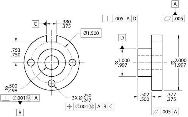
Geometric Dimensioning and Tolerancing (GD&T)
Geometric Dimensioning and Tolerancing is a system for detailing and communicating standard machining tolerances. Since there are many types of tolerances in many different types and shapes of parts, a standardized system helps the various parties involved in manufacturing communicate with each other. GD&T is the most widely used standard tolerance system in the world.
GD&T assigns symbols for different types of tolerances, along with a detailed set of rules for measuring each tolerance band.
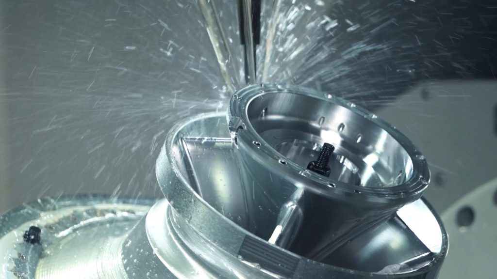
Common CNC Machining Tolerances
CNC machining is a broad field with many different processes under its umbrella. The CNC machining tolerances for each of these processes are different due to variations in the types of cutting tools used. Here are the standard CNC machining tolerances for common processes:
Router: ± 0.005″ or 0.13 mm
Lathe: ± 0.005″ or 0.13 mm
Router (gasket cutting tools): ± 0.030″ or 0.762 mm
Milling (3-axis): ± 0.005″ or 0.13 mm
Milling (5-axis): ± 0.005″ or 0.13 mm
Engraving: ± 0.005″ or 0.13 mm
Rail Cutting tolerances: ± 0.030″ or 0.762 mm
Screw Machining: 0.005″ or 0.13 mm
Steel Rule Die Cutting: ± 0.015″ or 0.381 mm
Surface Finish: 125RA
If you compare these values to alternative remanufacturing technologies, you will find that CNC machining processes have tighter tolerances.
Important Things to Remember When Working with Tolerances
When dealing with tolerances, knowing a few things up front can lead to a better end result, good planning and proper use of resources.
Do you need tight tolerances?
Because tolerances directly reflect the accuracy of a part, at first glance it may seem that tight tolerances are always better. However, for CNC machined parts, tight tolerances can increase the cost of production and result in a time-consuming process. Therefore, the use of tight tolerances should be considered when they are required.
Tight tolerances are generally required when a part is to be used in secondary assembly processes. Loose tolerances in these cases can lead to failure of an acceptable assembly. Therefore, there is a lot of focus on the tolerance band.
Another use case for tight tolerance machining is the design of prototypes of innovative parts. Designers expect the prototype to function exactly like the final product. Therefore, they use the tightest possible requirements.
Cost
To better optimize resources, manufacturers do not strive for the absolute tightest tolerances. Instead, they use the lowest tolerances that fit their budget. A good way to incorporate the budget factor is to plot the increase in cost against the decrease in tolerance band and find the acceptable range where these two values meet for the particular project.
Inspection
Most projects that use CNC machines or other manufacturing processes have a quality control phase to verify that the final product is within the acceptable range. If it is not within the acceptable range, the product is rejected; if very tight tolerances are used, the time spent in the inspection phase is significantly increased. In addition, complex equipment may be required to measure the tighter tolerance level.
Machining Methods
CNC machines are generally valued for their high precision and low specified tolerances. However, even within CNC machines, the type of machine used can significantly affect part tolerances. If you have CNC machines in your shop, determine the tolerance level of the machines and design the project accordingly.
Surface Roughness
Every surface has rough imperfections, no matter how smooth it looks. For some surfaces, such as polished natural stone, these aberrations are much smaller, resulting in less surface roughness. For others, such as wood, the surface roughness is much higher. Therefore, when choosing tight tolerances for CNC machining, consider the pre-existing surface roughness. Rough surfaces will cause difficulties when trying to achieve tight tolerances.
How do I find the right tolerance?
There are many ways to find the right tolerance for your part. Let’s go through these options one at a time:
Use a reputable CNC machining company
Outsourcing the project to a good CNC machining company can take the headache out of dealing with the technicalities of tolerances and many other things. MY Prototyping is one of the leading CNC service providers in this regard.
MY Prototyping’s CNC machining services are provided by a team of skilled experts and the most advanced machines and equipment available on the market. This means that not only do you have professionals suggesting the best tolerances to use, but you also have the best equipment to achieve those tolerances in real life.
Calculate tolerances yourself
In order to calculate the tolerance of the part yourself, you must first imagine how the part will be used. The functionality of the part will determine how much attention you need to pay to tolerances for the part. After that, you can use the general rules for determining tolerances.
Are there international standards for machining tolerances?
Yes, there are many international standards for machining tolerances. Geometric Dimensioning and Tolerancing (GD&T) itself includes seven different standards for measuring standard machining tolerances. Then there are the ISO 2768 standards.
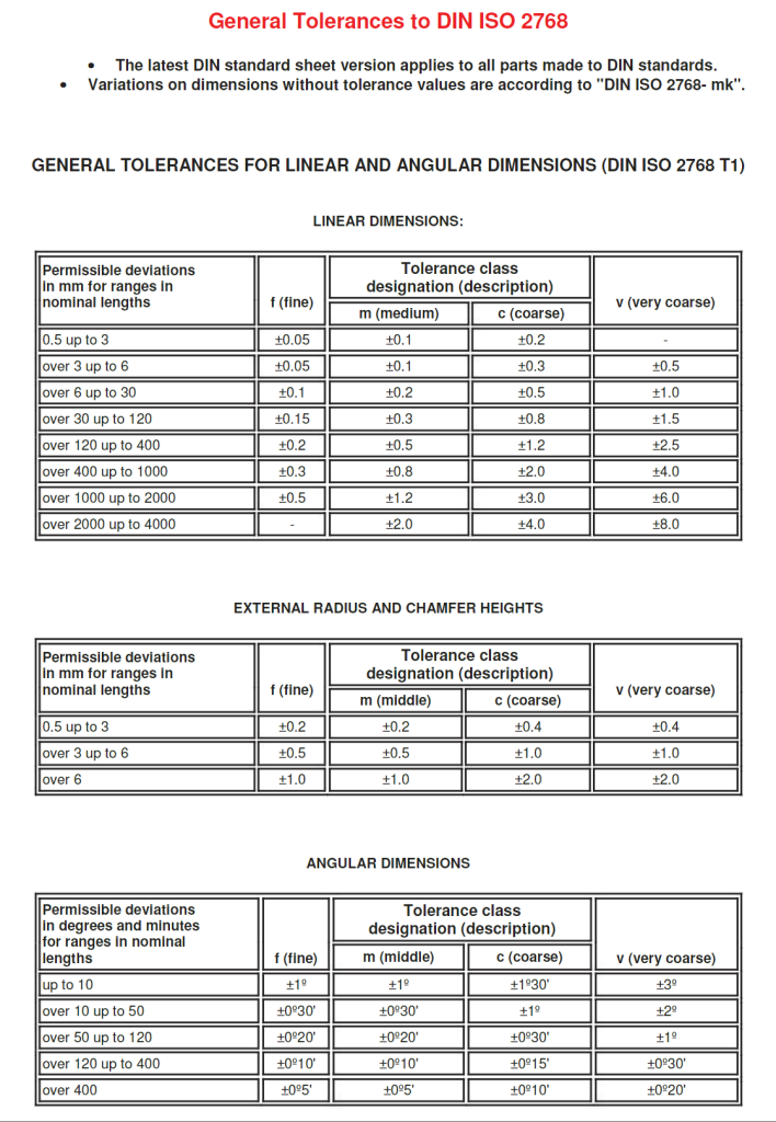
What is ISO 2768?
ISO 2768 is an international standard that specifies the general tolerances for manufacturing parts certified to international standards. It contains different classes within itself, such as
Linear dimensions
External radii and chamfers
Angular dimensions
General Straightness and flatness tolerances
General Squareness tolerances
General Symmetry tolerances
General Runout Tolerances
Tips for Tighter CNC Machining Tolerances
The following tips can help you achieve tighter machining tolerances and higher quality parts:
Remember that tolerances are not a one-size-fits-all designation. Calculate separate tolerances for different materials and for different applications. Standard tolerances for metal parts are +/- 0.005″ and for plastic parts are +/- 0.01″. These values may be more or less in practice due to varying geometric dimensions.
Choose has a manufacturing process that can achieve the tolerances you require. While tighter tolerance processes may be more expensive, they may be more cost effective overall due to better optimization.
Never underestimate the importance of parallelism and squareness tolerances. These tolerances should be prioritized because any shift in these values can affect every other value and even change the appearance of the part itself.
The Tolerance expectations should be consistent with the machinability of the material. Tighter tolerances require more work on the material. This extra work can be very difficult for materials that are already difficult to machine.
If the project does not require it, avoid using tight tolerances altogether. This can save significant costs in the project.
Place emphasize tolerances for the important features of the part, such as features that aid in assembly or features that carry the load. At the same time, tolerances can be ignored for some features, such as those for aesthetic purposes.
What is considered a tight tolerance in machining?
While there is no exact range of tight tolerances, anything around ±0.005″ is considered a tight tolerance for CNC machining. Tight tolerances can go as low as ±0.001″, below which machining becomes very difficult.
Importance of Machining Tolerances
The tolerance and dimensional accuracy of parts is much greater than meets the eye. Every manufacturing process, whether manual or CNC, has a certain amount of error, some more than others. Machining tolerances define the amount of error that can be tolerated.
Keeping tolerances in mind allows for the production of high quality parts. At the same time, ignoring tolerances can lead to serious manufacturing errors that result in the rejection of a large number of products or even entire batches.
The bottom line
Machining tolerances are an indispensable factor in manufacturing processes. While the degree of tolerance can vary from project to project, there are few applications where these values can be completely ignored.
Therefore, paying attention to the above information can save your project money and lead to a better quality result. If you feel that the concept of tolerance is too technical, difficult or hard to calculate for your particular project, MY Prototyping is here to help.
Frequently Asked Questions (FAQs)
Here are answers to some common questions about standard tolerances:
- What is the most difficult tolerance to machine?
Any tolerance below ±0.001″ is very difficult to machine. Keep in mind that this value is 25 microns, and one micron is one millionth of a meter. Therefore, such an extremely small value is rarely encountered in real-world applications. - What are the most common machining tolerances?
The most common machining tolerances are standard tolerances, which range from ± 0.005″ to ± 030″. These tolerances are used when customers do not have or do not specify their tolerance requirements.
Disclaimer of Warranty
The contents of this website are provided for informational purposes only. MY Prototyping makes no representations or warranties of any kind, express or implied, as to the accuracy, completeness or validity of the information. Any performance parameters, geometric tolerances, specific design features, quality and types of materials, or processes should not be inferred to represent what will be supplied by third party suppliers or manufacturers through MY Prototyping’s network. Buyers seeking instant quotes for parts are responsible for defining the specific requirements for those parts. Please see our Terms and Conditions for more information.